Background of ADI Digital Audio Transmission Scheme
Faced with the increasingly complex demands of users, automobile manufacturers have developed more ECU platforms to enhance the user experience. However, with the increase of these electronic systems, there is also an increase in the connection cables and costs between electronic systems, resulting in a decrease in fuel efficiency of automobiles. So the importance of reducing vehicle weight is self-evident. For car audio, traditional car manufacturers usually arrange the audio transmission in the car through a single analog cable and Ethernet. Due to the limitations of both, there is an urgent need for a digital audio transmission solution, which is why ADI's digital audio transmission solution has emerged.
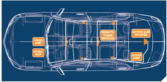
Figure 1 Car audio system
What is A2B
A2B is a digital audio transmission scheme that only requires outputting I2S, TDM, and other digital audio formats to the A2B chip at the audio output input end, which can be directly transmitted to the other end. The A2B receiver at the other end can then decode and output the audio. This solution can avoid the process of local analog-to-digital conversion and remote analog-to-digital conversion, thereby reducing audio loss. In the conversion process of AD and DA, regardless of the number of bits or the sampling rate, there will be a certain amount of audio loss.
Advantages of A2B
Using shielded twisted pair cables as wiring harnesses, reducing weight by over 75% (consumer grade cables do not require shielded wires)
The single point transmission distance is 15M, and the total cable length is 40M
50MIPS speed, capable of supporting up to 32 channels for both uplink and downlink
• Fixed delay, approximately 2 transmission cycles (50 μ s)
• There is a dedicated digital microphone interface
A2B can provide a current of no more than 300ma to the slave without using the local power supply of ECU
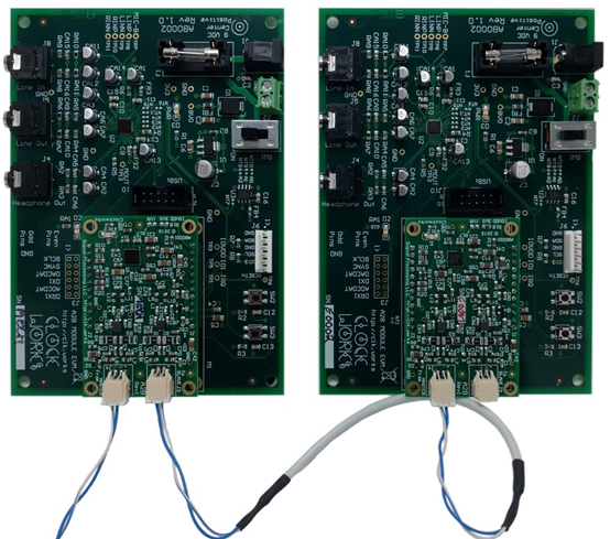
Figure 2: A2B Connection Physical Image
The hardware framework of A2B
A2B adopts a cascaded hardware architecture, based on chip receiver and transmitter components, achieving a cascaded effect by connecting AN, AP, BN, BP. We can expand the downstream microphone board, amplifier board, and so on that you need through a master in the front-end.
The complete system framework is shown in the following figure (Figure 3):
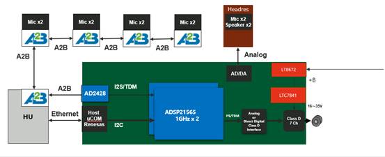
Figure 3 System Framework Routine
A2B internal building blocks, including PLL, digital audio interface, I2C interface VREG、 And the receiver and codec of AB end:
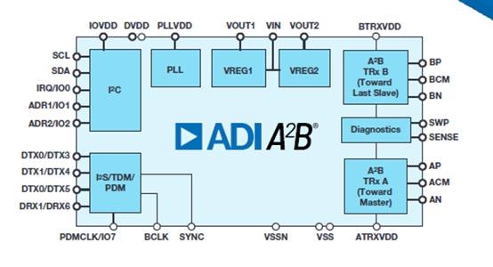
Figure 4 Internal components of chip
The development process of A2B
Firstly, it would be best to have a demo platform set up to facilitate our problem localization. At present, there are three main aspects of demand carriers, one is the Master host part, one is the microphone slave, and the other is the amplifier slave. The recommended connection order is: EVAL-AD2428WD1BZ -> EVAL-AD2428WB1BZ -> EVAL-AD2428WC1BZ, After the customer completes the design of the motherboard, conduct replacement testing to see if it can operate normally. If you are familiar with hardware principle design, you can skip it
The first and last nodes of the board only need to be used for the A and B ends. The focus of hardware design is on VSSN SENSE、SWP、 The design of the AB end periphery, under normal power and ground conditions, can directly affect whether communication is normal in four places.
The current development method for the software platform is SigmaStudio. You need to download the relevant plugins for A2B, install them, and then you can directly select the components to build. What we need to do is to create a task diagram and then configure and select each one separately. If using SigmaDSP, debugging can be done directly through USBI. If using other platforms and supporting C development, stack porting can be done by exporting configurations. There are two ways to boot the system to run normally: one is to write data in the form of I2C_command_st, and the other is to embed the underlying driver C file. It is recommended to first obtain a demo driver library from the installation directory document to make changes, and then directly configure it.
If the system can operate normally, it can expand other functions including interrupts, device control, etc. At the same time, for cars, it is also necessary to optimize EMI and EMC related issues, and take corresponding measures in PCB layout.
summarize
A2B can be split into three loops within a unified system, which is beneficial for adapting to different hosts, microphone boards, amplifier boards, etc. in other households, greatly saving development time. However, the overall software and hardware design of the A2B system is still quite complex, especially in terms of hardware principle design and layout, as well as software stack SDK configuration. This article is difficult to cover all the details.